Find the task quickly, then open a deep dive when you need every step.
Applies to RKCadTools for AutoCAD Plant 3D 2024 / 2026 / 2027. Load the DLL that matches your Plant 3D year.
No matching guide sections found. Try another search word.
Start Here
Use this section when opening the toolkit for the first time.
Open the toolkit
Open AutoCAD Plant 3D.
Open your Plant 3D project.
Type NETLOAD.
Select releases\<year>\RKCadTools.dll (for example releases\2026\RKCadTools.dll).
Use the new RKCadTools ribbon tab.
Prefer the autoloader bundle? Copy releases\<year>\RKCadTools<year>.bundle to %APPDATA%\Autodesk\ApplicationPlugins\ and AutoCAD loads the toolkit on startup — no NETLOAD needed.
If the ribbon is missing
Type this command in AutoCAD:
RKCADTOOLS_RIBBON
If it still does not appear, load the DLL again with NETLOAD.
AutoCAD locks loaded plugin files. Close AutoCAD before replacing DLL files in a folder that is already loaded.
For normal use, load the packaged DLL from releases\<year>. Developer builds are written under src\RKCadTools\bin\x64.
Recent updates: Color Sets, Linked P&ID Publish, Revision Manager, and Drawing List Generator are covered below. Spec Browser adds drag-and-drop insertion, Excel export, and advanced visible-column search. Data Manager adds explicit class loading, class-aware saved views, and Excel import/export. Assign Tag keeps separate P&ID and 3D field setups, while Quick Properties now uses Plant 3D’s persistent native Override state for eligible acquired properties.
Deep-Dive Guides
Open a focused walkthrough when the quick explanation is not enough.
Start with the Quick Guide for orientation. Each deep dive adds preparation, screenshots, safety checks, detailed steps, and troubleshooting for one larger workflow. You can also browse every guide from the Guides page.
Data Manager
Load, filter, edit, review, and exchange project data with Excel.
The toolkit is grouped into task-based ribbon panels.
Screenshot pending Full RKCadTools ribbon tab with every panel visible (Tags, Properties, P&ID Connectors, Pipe Specs, Data Manager, Weld Manager, Drawings, Data Bridge, Utilities). Capture at 2× scale, dark AutoCAD theme, PNG.
Panel
Buttons
Use it for
Tags
Assign, Tag Audit, Tag Settings, Renumber, Assign Next, Nozzle Number, OPC Number
Assigning tags, checking drawing or project tag quality, and managing tag numbers. Tag Audit, Renumber, Assign Next, Nozzle Number, and OPC Number are shown in P&ID drawings.
Properties
Quick Properties, Quick Settings
Opening the Quick Properties palette and choosing which properties are shown per class or family.
P&ID Connectors
OPC Manager, OPC Overview
Connecting and reviewing P&ID off-page connector pairs, including project overviews and Cluster Map visualization.
Pipe Specs
Spec Browser
Searching active project spec sheets across component rows, part sizes, item codes, descriptions, and custom spec columns.
Data Manager
Data Manager, Data Validator
Working with project data tables and comparing values across Plant, Excel, SQLite, SQL Server, or OData sources.
Weld Manager
Numbering Settings, Lock Weld Numbers, Renumber From Point, Lock All, Blank Numbers
Numbering or clearing 3D piping weld numbers. This panel is shown in 3D Piping drawings.
Drawings
Create Drawing → P&ID Drawing
Creating a registered P&ID drawing with a suggested file name based on drawings already registered in the project.
Data Bridge
Choose Data, Sync, Sync All Open, Setup, Data Sources
Interactively choosing external records for selected components or automatically synchronizing Plant 3D data from Excel, SQLite, SQL Server, or OData sources.
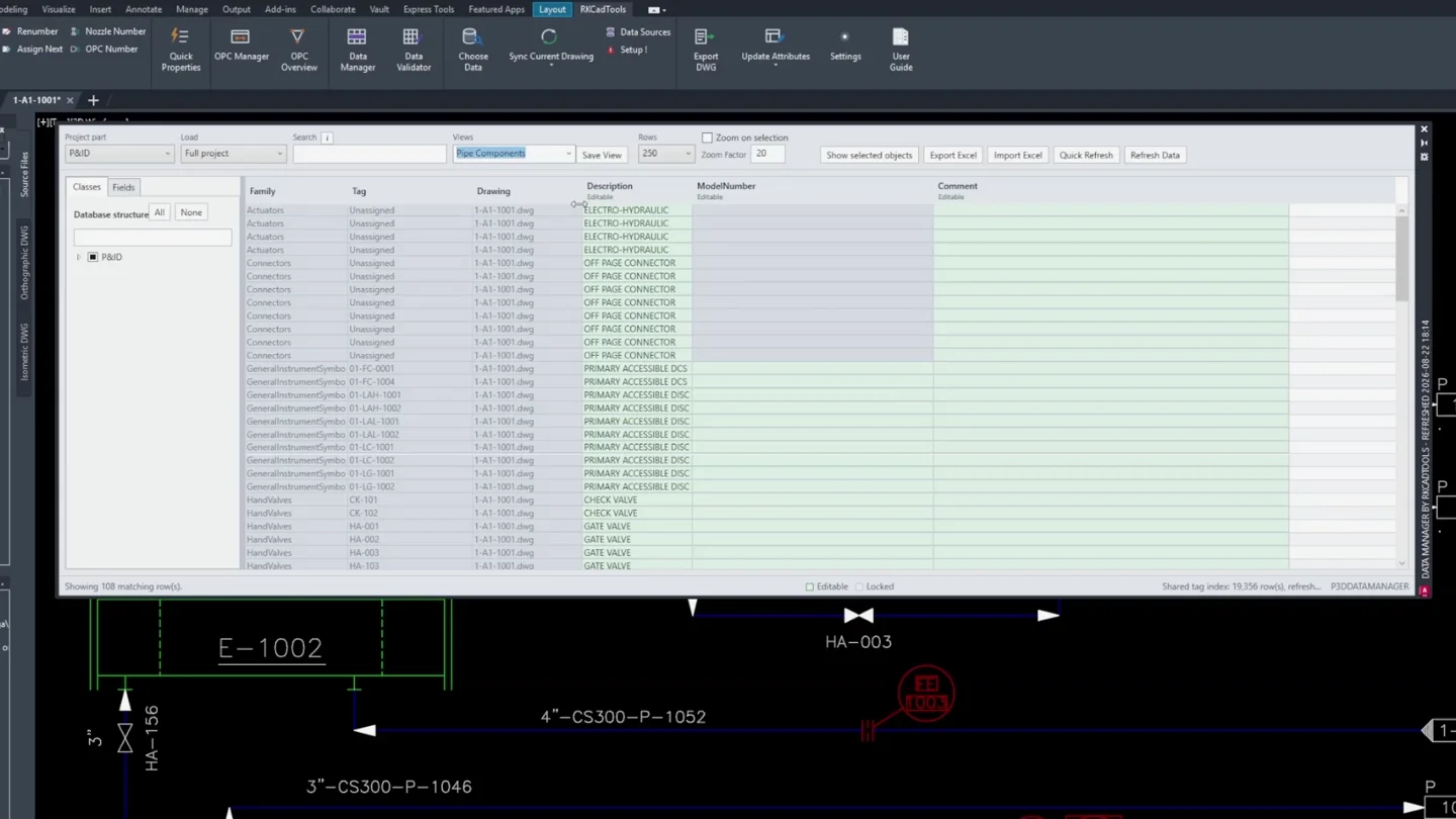
Choose P&ID or 3D Piping, then choose Current drawing or Full project.
Use the Classes tab to select one or more database classes.
Click Load selected data. If you change the class selection later, load again to update the grid.
Show the fields you need
Open the Fields tab.
Use the field search box to find a property.
Tick the fields you want.
Click Apply.
Save and reuse a view
Select the required classes and fields, then arrange or hide grid columns.
Type a name in Views and click Save View.
The view stores its class selection, visible fields, filters, and column layout. Saving also applies a pending class selection.
Edit a value
Show the field in the table.
Click a green editable cell.
Type the new value.
Hover over a pending cell, or select it, to compare the previous value, new value, and change source.
Click Review changes to search all pending changes and exclude individual items if needed.
Click Accept to write the remaining changes, or Discard to cancel them.
Exchange data with Excel
Filter the rows and fields to what you want.
Click Export Excel for a formatted workbook containing a hidden stable object key.
Edit only the unlocked green cells, then use Import Excel.
Click Review changes to compare old and new values, search the pending set, and exclude any change that should not be applied.
Click Accept. Unsafe or unmatched rows are skipped and marked in an .import-result.xlsx copy. Its RKCadTools Import Changes worksheet records each staged cell with its drawing, Plant row, class, property, previous value, new value, and source.
Review pipeline groups
Click Pipeline Groups.
Choose P&ID or 3D pipeline group data.
Edit writable fields in the table.
Click Update to apply pending changes to affected drawings.
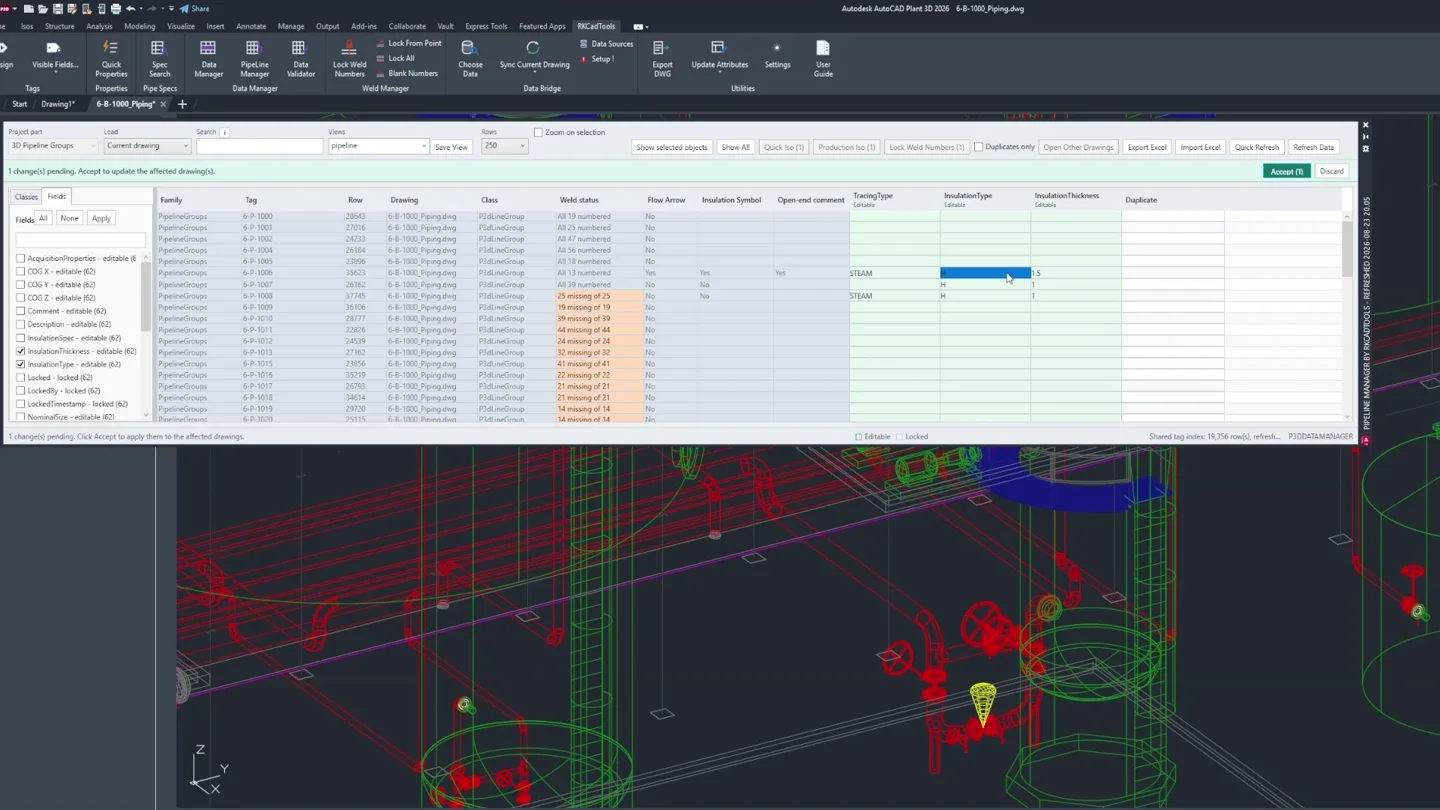
Pipeline Groups view for 3D Piping, with weld status and insulation fields ready to edit.
Pipeline Groups adds Zoom Lines, Assign Next Tag, and Update actions for group-level workflows. A Duplicate column and Duplicates only checkbox flag pipeline groups that span more than one drawing. Select a duplicate row and click Open Other Drawings to open each additional drawing and zoom to the matching lines. No database changes are made.
Search checks every loaded row but only the columns currently visible in the grid. Use spaces for AND, | for OR, quotes for exact phrases, or right-click the search box to insert a visible column name. Pasting rows or columns from Excel creates an OR list automatically.
Data Validator
Use this to compare property values across two or three data sources and find rows that disagree.
Screenshot pending Data Validator result grid after running a three-way comparison, with green (agree), pink (mismatch), and amber (missing key) rows visible. Capture at 2× scale, dark theme, PNG.
P3DVALIDATOR P3DVAL
A data source can be P&ID data, 3D Piping data, or an external source defined in Data Bridge (Excel, SQLite, SQL Server, or OData). Data C is optional: the validator runs a 2-way A vs B comparison until you pick a Data C source.
Set up a comparison
Click Data Validator in the Data Manager panel.
Choose a source under Data A and a matching Key A field.
Choose Data B and Key B.
Optional: choose Data C and Key C for a three-way comparison.
Click Load / Refresh to pull field metadata.
Pair the fields to compare
Open the Fields to Compare tab.
Click Add mapping.
Pick the Data A property and the matching Data B (and optionally Data C) property.
Use the search boxes above the grid to filter long field lists.
Repeat for every property that should agree across the sources.
Narrow scope before validating
Open the Data A, Data B, or Data C tab.
Tick the classes you want to include in Database structure.
Use Exclude key values matching regex to drop unwanted keys (for example \? to skip placeholder rows).
Click Apply to refresh the preview.
Run validation
Click Validate.
Read the row count, mismatch count, and value cells in the result grid.
Use the Search box (space for AND, | for OR, quotes for exact phrases, Field:value for one column) and the Status filter to focus on specific issues.
Tick or untick rows in the first column to mark which results to act on or export.
Zoom and export
Select a result row.
Click Zoom A, Zoom B, or Zoom C to focus the linked Plant object in the drawing.
Click Export Excel to share the filtered list. The workbook keeps the row status colors and the per-cell agreement colors.
Click Clear Results to start over without losing the source selection.
Save and reuse a selection
Type a name in the Selection box at the top of the window.
Click Save Selection.
Pick the saved selection later to restore sources, keys, class filters, regex, mappings, and result columns.
Use Clear C next to Key C to drop Data C from the active setup and fall back to A vs B.
%APPDATA%\RKCadTools\SavedViews\Validator
Row color
What it means
Green
All mapped values agree across the chosen sources. Fully matching keys normally do not appear in the results grid, so you will rarely see a green row.
Pink
A mapped value disagrees somewhere. The cell colors below show which side.
Amber
The key is missing in at least one source, or the key field is empty.
Purple
The same key appears more than once on a side.
Value cell color
What it means
Green
This value matches at least one other source.
Red
This value differs from every other source. With three sources this is the odd one out; with all three red, no two agree.
No tint
The field is not mapped for this side, so nothing was compared.
The most recent result is cached under %APPDATA%\RKCadTools\Plant3DDataValidatorResults.json and reopens automatically next time you launch the validator. Use Clear Results to delete it.
Validate on a copied project before running the validator against large live data sets so unexpected scope or regex filters do not surprise the team.
Use this for fast property changes on selected objects.
Screenshot pending Quick Properties palette docked next to a Plant 3D drawing, with an object selected and its editable (green) fields visible. Capture at 2× scale, dark theme, PNG.
Open Quick Properties
Click Quick Properties.
The palette opens immediately.
Select objects in the drawing to load their configured properties.
Edit the properties shown in the palette.
QEDIT
Choose shown properties
Select an object first so the tool knows which Plant database and class to use.
Click Quick Settings in the Properties panel.
Pick the class or family.
Select which properties should appear.
QEDITPROPS
Set a value at the command line
Run QEDITSET.
Select one Plant 3D or P&ID object.
Pick the editable property by number.
Type the new value. It is written immediately, without opening the palette.
QEDITSET
Number nozzles
Select or pick the nozzles.
Click Nozzle Number.
Enter the starting number.
QEDITNUMBER
Number off-page connectors
Select or pick off-page connectors.
Click OPC Number.
Enter the starting connector number.
QEDITOPCNUMBER
Quick Properties can include editable line-group properties when the selected object belongs to a line group. Use Quick Settings to choose visible and read-only properties per class or family.
In P&ID, selecting a primary line segment can show both the selected Primary row and its related Pipeline Group row. Editable Pipeline Group properties can be changed directly from Quick Properties. Tags, formulas, counters, Plant 3D system fields, and acquired values without native Override support stay locked.
Acquired properties remain locked until Plant 3D reports that they can be overridden. Right-click an eligible value and choose Override property. Quick Properties switches and verifies Plant 3D’s native Override mode before writing; the yellow override state is stored in the project and survives AutoCAD restarts.
The Nozzle Number and OPC Number buttons are on the Tags panel and are shown in P&ID drawings.
Tags
Use this panel when assigning or checking Plant 3D tags.
Screenshot pending Tag Audit — Active Drawing tab, with missing and duplicate tag rows highlighted. Capture at 2× scale, dark theme, PNG.
Assign a tag
Select the object.
Click Assign.
Fill in the tag and configured extra fields.
Confirm the Plant 3D tag command.
ATX_ASSIGN
Check tags in one drawing
Open the drawing.
Click Tag Audit and use the Active Drawing tab.
Review missing tags, duplicate tags, and question marks.
Use Assign to edit the selected tag. P&ID lines open Autodesk’s native Assign Tag dialog.
ATX_TAGAUDIT
Assign next available numbers
Click Assign Next.
Pick objects one after another.
The tool assigns the lowest available number for each tag prefix.
ATX_ASSIGNNEXT ATX_AUTONUMBER
Refresh acquired drawing data
Open Tag Audit on the Active Drawing tab.
Click Refresh Acquired.
Plant 3D refreshes acquired and calculated properties in the current drawing. Tags that use those properties are updated, and Tag Audit rescans when the command finishes.
This does not assign new tags or rebuild tags after tag-format changes. Collaboration and Vault drawings must be writable or checked out.
PLANTREFRESHACQPROPERTY
Replace existing tag numbers
Select the objects and click Renumber.
Review the confirmation explaining the left-to-right processing order.
The tool clears and replaces each number. If assignment fails, it restores the previous value.
ATX_RENUMBER ATX_CLEARNUMBER ATX_CLEARNUM
Check tags in the project
Open the Plant project.
Click Tag Audit and select the Project tab.
Review drawing-level and class-level tag status.
Double-click a drawing or use Open in Tag Audit for row-level fixes.
ATX_PROJECTAUDIT
Choose tag fields
Open Tag Settings and choose Visible Fields.
Choose P&ID or 3D Parts. Each scope has its own class tree and field configuration.
Choose which extra fields appear in the tag window for that scope.
Save the configuration.
ATX_CONFIG
Take over the native tag command
Open Tag Settings and choose Native Takeover.
When enabled, the native Assign Tag command opens Assign Tag Extended instead.
Choose Native Takeover again to switch back to the native dialog.
ATX_TAKEOVER
The Project tab can export the audit result and open drawings directly in the Active Drawing tab. Use the audit filters to control which source families and classes are included.
In Tag Audit, Assign Next is available only when all selected rows belong to Inline Assets, Instrumentation, or Equipment. It is hidden for pipelines, nozzles, connectors, annotations, mixed unsupported selections, and unknown source families.
Tag Audit, Renumber, and Assign Next are shown in P&ID drawings. The original Clear Number command remains available for command-line and macro compatibility.
P&ID Connectors
Use this to work with off-page connector pairs.
Screenshot pending OPC Manager palette showing a drawing’s unconnected connectors and suggested partners. Capture at 2× scale, dark theme, PNG.
Connect or review off-page connectors
Click OPC Manager.
Search or choose the drawing.
Review unconnected connectors and suggested partners.
Connect or disconnect the connector pair.
PIDMANAGER
Review the project overview
Click OPC Overview.
Review drawing-to-drawing connector flow and unconnected connector counts.
Switch to Cluster Map when you need a draggable visual map of drawing relationships.
Open or zoom to a connector from the overview when a drawing needs correction.
P3DOPCOVERVIEW P3DOPC
OPC Manager and OPC Overview are docked palettes. They can stay open while you move between drawings and review connector status.
Pipe Specs
Use this to search the active project’s spec sheets.
Screenshot pending Spec Browser search results with a matching component row selected and Insert in Model highlighted. Capture at 2× scale, dark theme, PNG.
P3DSPECBROWSER
Search a spec sheet
Click Spec Browser in the Pipe Specs panel.
Choose the active spec or all registered specs and optionally filter by component type.
Search with spaces for AND, | for OR, quotes for exact phrases, or a column-qualified term such as Size:DN100. Right-click a column header to target it, or paste an Excel list.
Use Columns… to choose the visible result columns. Search and export use them in their current order.
Review matching component rows, part sizes, item codes, descriptions, and custom spec columns.
Insert or export results
Select a result and click Insert in Model, double-click the row, or drag it into the active Plant 3D model.
Complete placement using the normal Plant 3D insertion prompts.
Click Export to Excel to create a formatted workbook from the visible result layout.
Spec Browser follows the spec files registered in the active Piping project database. If a registered spec or its companion .pspc database cannot be opened, use the Warnings button for the exact path and reason.
When the palette is narrow, Spec Browser switches to a compact layout: Spec and Type stay side by side, Search fills the next row, and Insert, Refresh, Export, and Columns move into the … menu. Selected part values start collapsed to preserve grid space. Compact and wide modes remember their own visible columns, order, and widths.
Weld Manager
Choose weld classes and numeric series, then fill missing numbers or review a new sequence in the active 3D Piping drawing.
Before numbering: WeldNumber must allow manual entry. For ISO output, select ID: Weld Number Property for Weld ID (Shop) and/or Weld ID (Field) in Project Setup → Isometric DWG Settings → Annotations → Table ID’s. Automatic ISO IDs can display a different sequence.
Choose classes and numbering series
Open Numbering Settings.
Keep the default to number all detected weld classes in one shared series per pipeline, or enable Choose weld classes and numbering series.
Add a named series and check its weld classes. Multiple classes in one series share a counter; separate series have separate counters.
Set Start number. Review the numeric example and save.
Weld numbers are positive integers without leading zeros. Example: one shared series produces 1, 2; separate series can each start at 1. Use one shared series when numbers must be unique across classes. A class can belong to one series. Unselected classes are skipped.
WM_WELDSETTINGS
Lock missing weld numbers
Click Lock Weld Numbers.
Pick an object on the pipeline.
Review old and new numbers, class, row ID, Drawing No. and DWG filename in the preview. Apply the changes, or cancel to leave the drawing unchanged.
Review the result and save/check in through the normal Plant 3D workflow.
Existing values stay unchanged. Blank numbers continue above the highest matching number in each series on that pipeline in the active DWG. Numbers in other DWGs do not affect the counter. “Lock” fills values; it does not set a separate read-only flag.
WELDMANAGER_LOCKWM_LOCKWELDNUMBERS
Automatically number new welds
Enable Automatically number new welds after modeling commands in Numbering Settings.
Create new welds while modeling.
Check the automatic numbering result after the command ends.
Enable this in WM_WELDSETTINGS; no ISO, start point or prior Renumber From Point run is required. The same classes and series rules apply in the active DWG. Only new blank weld rows are numbered; existing numbers and older blank rows are preserved. Undo/Redo and failed or cancelled commands do not trigger numbering. Automatic numbering runs without a preview dialog after successful modeling commands. Commands without new Plant objects do not trigger a drawing scan, and completed objects leave the queue immediately. Numbering may be a separate undo operation.
Renumber from a point
Click Renumber From Point.
Pick an object on the pipeline and the start point.
Review Drawing No., DWG filename, class, row ID, old number and new number. Drawing No. falls back to the filename when unavailable.
Apply the plan or cancel without changing numbers.
This replaces existing numbers for the selected classes in the active drawing, using each series’ start number. Numbers in other DWGs do not affect this sequence. The existing command aliases remain available.
Lock All asks you to continue before filling blank numbers on all pipelines in the active drawing with your numbering rules. Existing values are kept.
Blank Numbers clears editable weld numbers on the selected pipeline for all weld classes, irrespective of class selections in Numbering Settings.
WM_LOCKALLWELDNUMBERSWM_CLEARWELDNUMBERS
Check weld numbers
Check Weld Numbers reports duplicates within each series on the pipeline in the active DWG. Existing 001 and 1 values represent the same number in that series.
WM_WELDDIAG
Drawing-based changes: only graphical welds in the active drawing are changed through Plant 3D’s API. The toolkit does not write directly to project databases; Plant manages the linked project data. Protected, acquired, calculated and generated WeldNumber fields are rejected. Test on a project copy first.
Use this to choose external records for selected components or automatically synchronize Plant 3D data from Excel, SQLite, SQL Server, or OData.
Screenshot pending Data Bridge Preview grid showing the before/after values for a pending sync, prior to clicking Apply. Capture at 2× scale, dark theme, PNG.
Configure an interactive lookup
Click Setup, then add or select a configuration.
Choose its data source and set Run mode to Interactive lookup.
Add the external-to-Plant property mappings that should be written.
Click Configure filters and displayed columns.
Add the required filters and check only the columns users should see in the result table.
P3DBRIDGE_CONFIG
Choose data for components
Preselect one or more compatible components, or click Choose Data and select them afterward.
If several lookup profiles apply, choose the required profile.
Use the configured dropdown filters and search box to narrow the external rows.
Select a row and review the before-and-after property preview.
Click Use row for this group. If only one row is visible, it is selected automatically.
Complete any remaining groups, then click Apply all groups.
P3DBRIDGE_LOOKUP
Interactive filter types
Filter type
How it works
Fixed value
A hidden administrator value, for example Varekategorikode = 2203.
Component property
Matches an external column against a selected component property, for example external Size against Plant Size.
User choice
Shows a dropdown containing available source values, for example Supplier.
Component-property filters also create groups. A mixed DN50/DN80 selection is therefore handled as separate lookup groups when Size is configured.
Interactive write rules
The chosen row is applied to every component in its group.
NULL, blank, or missing external values are ignored and never clear existing content.
Writable properties are applied even if another mapping is read-only or acquired.
Skipped read-only and acquired properties are listed in the completion report.
Selected components must use the same Plant class and project section. Configured component-property differences are handled as groups.
Set up a sync
Click Setup.
Create or select an Excel, SQLite, SQL Server, or OData data source.
Choose the table, view, or sheet.
Choose scope, classes, and conditions.
Map external columns or static values to Plant 3D or AutoCAD properties.
P3DBRIDGE_CONFIG
Preview before syncing
Click Preview.
Review the before→after grid of every change the sync would make.
Click Apply all to write every listed change. To write only selected changes, use Accept first and then Apply (N); close the window to discard the preview.
Nothing is written until you click Apply.
P3DBRIDGE_PREVIEW
Manage data sources
Click Data Sources.
Add or edit Excel, SQLite, SQL Server, or OData sources.
Preview the source rows before mapping.
P3DBRIDGE_DATASOURCES
Sync the active drawing
Open the drawing.
Confirm the setup is correct.
Click Sync.
P3DBRIDGE_SYNC
Sync open drawings
Open the drawings that should be processed.
Click Sync All Open.
Let the tool activate, save, and sync each drawing.
P3DBRIDGE_SYNCOPEN
Control sync order and matching
Use Enabled to keep a setup saved without running it.
Use Priority so lower-numbered configurations run first.
Use condition logic for all conditions or any condition.
Choose whether empty external values should be written or skipped.
Use Data Bridge carefully. Test on a copied project before changing live project data.
Safest first setup: start with one class, one unique key condition, and one non-critical property. Run Preview, check every before→after value, and keep Show Sync Preview enabled until the result is trusted.
Automatic sync configurations run with Preview, Sync, Sync All Open, or sync-on-open. Interactive lookup configurations run only from Choose Data and never participate in automatic sync.
Data Bridge uses two config files: a shared/admin file (Plant3DDataBridge.json) and a per-user file (Plant3DDataBridge.user.json). The plugin always writes to the user file; the admin file is read-only from the plugin. Both are merged at sync time — data sources and configurations from both run together. By default both files are stored in a project-specific folder under %APPDATA%\RKCadTools\DataBridge\Projects. Use Settings → Shared Admin Folder to place the shared/admin Data Bridge file in <sharedFolder>\Projects\<projectName>\Plant3DDataBridge.json. A short project-ID suffix is added only when two different projects share the same name.
Color 3D Plant objects by a property value while you review a piping drawing.
Set a color for each property value, then choose how empty, other, and non-Plant objects appear.
Create and apply a set
Open a 3D Piping drawing and choose Color Rules → Settings.
Click New, name the set, and choose whether values come from a component property or a pipeline group property.
Choose Color by. Use Scan drawing to collect values, or add them yourself. Assign colors individually or use Auto-assign palette.
Choose optional colors for empty values, unlisted values, and non-Plant objects. Set non-Plant transparency if needed.
Click Save, then select the set from the Color Rules ribbon menu. Use Show Legend to review the active colors; choose Color Rules Off to return to normal display.
Local, shared, and plotting
Local sets can be edited. Shared sets are read-only in the list; use Duplicate to Local to make an editable copy.
Colors are display-only by default. Tick Include in plot only when the plotted output should use the set.
Color Sets apply to 3D Piping drawings, not P&IDs, orthos, or isometrics. The display colors do not change Plant project properties.
Linked P&ID Publish
Publish a P&ID set with clickable off-page connections in a multi-sheet PDF.
Choose the sheet scope and whether OPC connections should become PDF links.
Publish a linked PDF
Click Linked P&ID Publish on the ribbon.
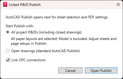
Choose All project P&IDs to include paper layouts from registered P&IDs, including closed drawings, or choose Open drawings for the standard AutoCAD Publish sheet list.
Leave Link OPC connections selected when reviewers need clickable off-page connections.
Click Open Publish. Review sheets, order, page setups, and PDF settings in AutoCAD Publish, then publish a multi-sheet PDF in the foreground.
Open the resulting PDF and test the links between sheets.
Before you publish
All-project scope selects paper layouts and excludes Model. Every selected project DWG must be available locally and have a paper layout.
If the output PDF is locked by a viewer, the linked result is saved as a separate _linked.pdf file. Check the report beside the output if a sheet or link could not be processed.
RKCADTOOLS_LINKEDPIDPUBLISH
Revision Manager
Keep drawing revision history and mapped title blocks in sync.
Add a revision note, then save and synchronize it to the drawing title block.
Add a revision
Open Revision Manager or choose Add Revision Note from its ribbon dropdown.
Review the next revision code and date; enter the description and initials.
When working in Revision Manager, click Add to stage the row, then Save & Sync to write the DWG history and update configured paper-space title blocks.
Use Edit or Delete to maintain the history. Run Sync again after reviewing any manually changed title-block attributes.
Configure the title block
Open Revision Manager Configuration and select the title block.
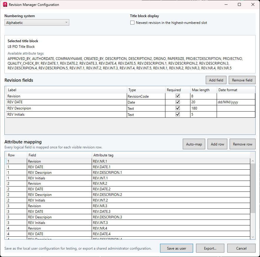
Choose alphabetic or numeric numbering, define the revision fields, and map each visible revision row to its title-block attribute tags. Auto-map can detect numbered tags.
Save as user to test locally, or Export a shared administrator configuration.
Example title block after revision B is added: the earlier A entry has moved up one visible row, and the new entry appears below it. Row order follows the configured title-block mapping.
Full revision history: A title block shows only as many revision rows as it has configured slots. When older revisions move beyond those visible rows, they remain in the drawing history and can still be viewed in Revision Manager.
Map the fields and revision slots used by your project title block.
RKREVISIONRKREVADDRKREVCONFIGRKREVSYNC
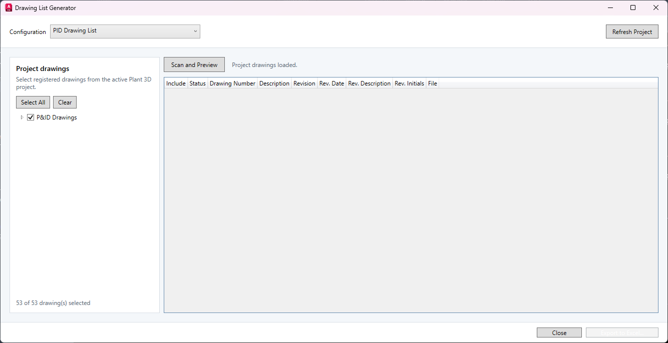
Drawing List Generator
Build an Excel drawing list from registered Plant 3D project drawings.
Select project drawings, scan their saved DWGs, review the preview, and export the list.
Create and export a list
Choose a configured profile from the Drawing List Generator ribbon dropdown.
Select drawings or folders in the active project’s drawing tree.
Click Scan and Preview. Review the status and the drawing number, description, latest revision, date, description, and initials columns configured for the profile.
Clear Include for rows you do not want, then click Export to Excel to create the .xlsx file.
Administrator setup
In Settings → Drawing Lists → Configure Drawing Lists, create a profile and map Excel columns to title-block attribute tags or Revision Manager fields. Choose Revision Manager fields such as revision code, date, description, and initials to bring the latest revision into the drawing list. The generator reads the latest saved revision from the drawing history; when no RKCadTools history exists, it can use the newest visible mapped title-block row. Save the profile in the shared admin folder so it appears in the ribbon.
Save edits in source drawings before scanning. Unavailable DWGs, missing title blocks, and missing revision values appear as preview warnings; the scan does not save the drawings.
RKDRAWINGLIST
Create Drawing
Create registered P&ID, Ortho, and 3D drawings with independent project-specific numbering.
Screenshot pending Create Drawing dialog with the next-number suggestion and the destination folder tree visible. Capture at 2× scale, dark theme, PNG.
Create a project drawing
Open Create Drawing and choose P&ID Drawing, Ortho Drawing, or 3D Drawing.
Use the next number (highest existing number plus the configured step), choose an available gap, or enter another file name.
Choose a destination from that drawing type’s searchable folder tree. The last location is remembered separately per type, and New Folder can create a child through Plant 3D.
A file name already used by the same registered drawing type is blocked.
Click Create, or Create & Continue to create the drawing and keep the dialog open for the next one.
Select P&ID, Ortho, or 3D and assemble an independent name from ordered segments.
Use Fixed/Separator for constants, FreeText or Choice for user input, and ProjectLookup or Date for generated values. Add at most one Counter when automatic next-number and gap suggestions are wanted; omit it for counterless names.
Edit or reorder segments, select folder or whole-project number scope, and review the generated read-only pattern.
Enable each required drawing type. Existing registered names are scanned within the matching project part.
Test the local draft, then export and deploy the shared JSON through the normal ACC/Vault project administration workflow.
RKDRAWING_CONFIG
The same segment definitions build the Settings preview and the Create Drawing form. FreeText becomes a validated text field. Each Choice row has a description shown in the dropdown and a separate value inserted into the file name. Project/date/counter values are generated automatically.
The Drawings panel shows only drawing types with a complete enabled configuration and a loaded matching project part. RKCadTools checks the file name again immediately before Plant 3D’s project API registers the drawing.
The number is a convenience suggestion, not a central reservation. Verify the workflow on a copied project before using it in production.
Utilities
Use this for drawing utilities and toolkit settings.
Screenshot pending Update Blocks — Batch Edit tab showing the diff grid (red = missing file/block, green = pending changes). Capture at 2× scale, dark theme, PNG.
Tool
Use it for
Command
Activate License
Activate the RKCadTools license on this workstation. The button is shown while no valid license is installed. RKLICENSE_STATUS shows the current license state.
RKLICENSE_ACTIVATE
Export DWG
Export selected P&ID or Plant 3D drawings to plain AutoCAD DWG copies.
P3DEXPORTACAD
Update Blocks
Update attributes, batch-edit attribute values with Excel, or redefine an existing block from a source DWG.
P3DUPDATEBLOCKATTRIBUTES
Settings
Open, export, import, and edit project and user configuration files.
P3DUTIL_SETTINGS
Update from one source block
Open Update Blocks.
Choose the source drawing and click Pick Block.
Pick the title block or block reference that contains the attributes to copy.
Edit the New Value column and tick the attributes to update.
Select target drawings. Add DWGs, add a folder, or load paths from a .txt, .csv, or .lst list when needed.
Choose whether to update the source drawing, update all matching blocks in each drawing, and save drawings after the update.
Click Update Attributes and review the result grid.
Batch edit with Excel
Add the DWG files to edit.
Pick the source block from the first DWG, or type the exact block name.
Click Read Attributes to preview values across the files.
Export the preview to .xlsx, edit the attribute values, and import the edited workbook.
Review the diff. Red rows are missing files or missing blocks; green rows contain changes that can be applied.
Click Apply Changes and export the CSV result log when a record is needed.
Redefine blocks from a source DWG
Open Update Blocks and switch to Redefine Blocks.
Add the target DWGs where an existing block definition should be replaced.
Pick the target block from the first target DWG, or type the exact block name.
Pick the source DWG and the source block definition that should replace the target.
Click Preview Targets to check missing, read-only, and matching drawings before writing.
Click Redefine Blocks and review the result grid. Export the CSV log when a record is needed.
Shared and project files
Data Bridge is project-specific. Its default shared/admin JSON and per-user JSON are stored under %APPDATA%\RKCadTools\DataBridge\Projects\<projectName>-<hash> so Plant 3D cleanup does not remove them.
When Shared Admin Folder is set, this project’s shared/admin Data Bridge file is read from <sharedFolder>\Projects\<projectName>\Plant3DDataBridge.json. A project.identity.json marker verifies the Plant project identity, and a short project-ID suffix is used only for duplicate project names. Existing hash-named folders are not migrated automatically. The matching Plant3DDataBridge.user.json file stays in each user’s AppData folder.
Admin vs user configs
Every RKCadTools feature uses two config files: a shared/admin file (<Feature>.json) and a per-user file (<Feature>.user.json). The plugin always writes to the user file; the admin file is maintained by an administrator and read-only from the plugin.
At runtime both files are merged: lists (data sources, configurations, columns) are concatenated, dictionaries (class entries, scope settings) are unioned by key with user entries winning on conflict, and scalar flags take the user value when present.
Feature
Shared (admin)
Per-user (plugin writes here)
Data Bridge
Plant3DDataBridge.json
Plant3DDataBridge.user.json
Assign Tag Extended
AssigntagExtended.json
AssigntagExtended.user.json
Quick Edit
Plant3DQuickEdit.json
Plant3DQuickEdit.user.json
Data Manager
Plant3DDataManager.json
Plant3DDataManager.user.json
P&ID Connector Helper
PIDConnectorHelper.json
PIDConnectorHelper.user.json
An admin can redirect all shared/admin settings in one step via Settings → Shared Admin Folder → Set Location. RKCadTools then reads admin-managed views from <sharedFolder>, feature admin configs from <sharedFolder>\Admin\<Feature>.json, and Data Bridge admin configs from <sharedFolder>\Projects\<projectName>\Plant3DDataBridge.json. Users’ own edits always go to their personal .user.json files.
Saved views (admin + user)
Saved views (Data Manager views, Export selections, Validator profiles) also support the admin/user split. User views are saved in the personal views folder (%APPDATA%\RKCadTools\SavedViews) unless Saved Views points to another personal or team folder. Admin-managed views come from the root of the Shared Admin Folder and are loaded read-only alongside each user’s personal views. Views with the same name in the user folder override admin views.
Data Manager views are grouped by data source below the views root:
DataManager\PnId — standard P&ID views.
DataManager\Piping — standard 3D Piping views.
DataManager\PnIdPipelineGroups — P&ID Pipeline Group views.
DataManager\PipingPipelineGroups — 3D Pipeline Group views.
For admin-managed views, these folders are below the Shared Admin Folder. Personal views use the same structure below the configured Saved Views folder. A personal scope folder is created automatically when its first view is saved; an administrator can create the corresponding shared folder when publishing an admin view.
User files
User-specific JSON files are stored under %APPDATA%\RKCadTools. This includes Quick Properties, Assign Tag Extended, Data Manager, Cross Navigation, and PID Connector Helper settings. Data Bridge user files are stored per project under %APPDATA%\RKCadTools\DataBridge\Projects\<projectName>-<hash>. Each feature has a .json (shared/admin) and a .user.json (personal) file; RKCadTools writes to the personal file.
Update Blocks can write changes back to DWG files. Test on copied drawings first when setting up a new title block, block redefine, or batch edit.
Reports
Build Excel reports from saved project data and compare matching runs.
Build a report
Save the source drawings and open Reports from the ribbon.
Choose an installed Autodesk Report Creator template.
Select Whole project, Current drawing or Selected drawings.
Click Build report. Review the completed Excel output and its entry in history.
Autodesk Report Creator must be installed. Reports use saved project data; unsaved drawing edits are not included.
Compare matching runs
The first successful report establishes a baseline. Build the same template again with the same drawing selection to compare against a matching previous run. Review changed, added and removed rows, and use Open change report to open the Excel comparison.
An unambiguous worksheet and key can be selected automatically. If the report has ambiguous keys, missing headings or duplicate values, configure the comparison first. Changing a tag used as a key can appear as a removed and added row.
Report storage: Use Settings → Reports to choose the output location. The default is the project’s Related Files/RKCadTools/Reports folder. Changing the location leaves existing history in its original folder.
RKREPORTRKREPORT_SETTINGS
P&ID Palette Builder
Organize project symbols into portable Plant 3D tool palettes.
Build a portable palette
Open a registered P&ID drawing and choose Admin Tools → P&ID Palette Builder.
Arrange the project symbols with headers and separators, and review their icons.
Validate the palette against the current project setup.
Use Save Configuration for the draft and Build Portable Package for the standard XTP palette package.
Test in Plant 3D
On a copy of the project, choose Test in Plant 3D to load a native preview palette. Open Tool Palettes with Ctrl+3 and place test symbols through Plant 3D.
After changing the draft, choose Update test palette. Use End test to remove preview palettes. Objects you placed remain in the drawing; remove them through the normal drawing workflow. Testing does not replace saving or exporting the palette.
RKPIPALLETTEBUILDERRKP3DPIDPALETTE
Troubleshooting
Common problems and what to do next.
The ribbon is missing
Type RKCADTOOLS_RIBBON. If that does not help, use NETLOAD and load RKCadTools.dll again.
A tool says there is no Plant 3D project
Open a Plant 3D project and make sure the active drawing belongs to that project.
Data Manager opens drawings while browsing
Turn off Zoom on selection. When this is on, selecting a row can open the drawing and zoom to the object.
A field is locked
Plant 3D controls which properties can be changed. Tags must be changed with ASSIGNTAG or PLANTTAG. System-managed fields may stay locked.
Settings are not where I expected
Every feature uses two config files: <Feature>.json (shared/admin, read-only from the plugin) and <Feature>.user.json (personal, where the plugin writes). Feature files live under %APPDATA%\RKCadTools by default. Data Bridge is project-specific and defaults to %APPDATA%\RKCadTools\DataBridge\Projects\<projectName>-<hash>. Use Settings → Shared Admin Folder to point admin views, admin configs, and Data Bridge admin configs to one shared folder. Use Settings → Saved Views when you only want to change where personal saved views are stored.
Data Validator shows no results or far too many
Check that Key A, Key B, and (if used) Key C all point to fields that contain the same kind of identifier. Then check the class filter on each Data tab and the Exclude key values matching regex box. Click Load / Refresh after changing sources so metadata is reloaded before validating.
I want to drop Data C without losing my A and B mappings
Click Clear C next to Key C. The validator falls back to a 2-way A vs B comparison. FieldC entries on existing mapping rows are wiped so old C values are not silently re-applied if you pick a new Data C source later.
The build folder cannot be overwritten
AutoCAD has loaded the DLL from that folder. Close AutoCAD, or build to a fresh folder and load that new DLL.
Your privacy, your choice
We use essential cookies to keep RKCadTools running. With your permission, we also use analytics and marketing cookies to understand what helps Plant 3D teams and improve the site.
Cookie Policy
Cookies are small text files that can be used by websites to make a user's experience more efficient. The law states that we can store cookies on your device if they are strictly necessary for the operation of this site. For all other types of cookies we need your permission. This site uses different types of cookies. Some cookies are placed by third party services that appear on our pages.
Necessary cookies help make a website usable by enabling basic functions like page navigation and access to secure areas of the website. The website cannot function properly without these cookies.
Marketing cookies are used to track visitors across websites. The intention is to display ads that are relevant and engaging for the individual user and thereby more valuable for publishers and third party advertisers.
Preference cookies enable a website to remember information that changes the way the website behaves or looks, like your preferred language or the region that you are in.