
P&ID Area Boxes in AutoCAD Plant 3D
How to draw a closed area in a P&ID drawing and let valves, instruments, and other objects inside it inherit the area’s chosen properties.
What does this feature do?
An Area object acts as a geometric data source. When Data Bridge syncs the drawing, it finds each target object’s reference point, determines which closed area boundary that point falls inside, and copies the properties you’ve mapped.
AreaNo = 120
AreaDescription = Utility
Is the object’s reference point inside?
AreaNo = 120
AreaDescription = Utility
AreaNo = 120
AreaDescription = Utility
This is a copy — not Plant 3D acquisition
Values are written to the target object’s own, editable Plant 3D properties. If you later change the area’s value or move an object, Data Bridge needs to run again.
Use this guide when the drawing position is the rule
Choose Area (geometric) when objects should receive values because they are inside a drawn P&ID zone: for example, an area number, plant section, or service. If the value should come from an Excel row, a database record, or an OData feed, use the automatic sync guide instead. For a one-off user choice from external data, use Data Bridge’s Interactive lookup mode rather than an automatic sync.
This needs to already exist in the project
The Area class itself and its properties are created by the project administrator in Plant 3D. RKCadTools does not create classes, symbols, or rows in the project database.

For example PidArea, created through the project’s normal class setup.

For example AreaNo and AreaDescription.

The same or matching editable fields need to exist on the classes that will receive the values.

The Plant-linked Area object needs to be a closed Polyline, Polyline2d, or Polyline3d with at least three points.
Check the geometry carefully
It’s not enough for a block to look like a box. The entity the Area row is linked to must itself be a closed polyline. An open polyline, a loose rectangle frame, or a plain BlockReference is ignored by Area sync.
Setup, step by step
Create the Area class once
This is normally a job for a project administrator or CAD coordinator.
- Open Plant 3D Project Setup and use your project’s normal workflow to create a P&ID class, e.g.
PidArea. - Add the properties an area should provide, e.g.
AreaNoandAreaDescription. - Make sure the receiving classes have editable target properties. The names can differ; the mapping connects them later.
- Set up the graphical placement so the inserted Area is registered in Plant 3D and has a closed polyline as its linked drawing entity.
Check: when you select the boundary in the drawing, Plant 3D should show the Area class’s properties. If it doesn’t, the boundary isn’t linked to the right Plant row.
Place and fill in the area box
Insert an Area using Plant 3D’s normal component workflow, and draw the boundary around the area that should share properties.
- Confirm the polyline is closed and has at least three corners.
- Fill in the Area object’s values, e.g.
AreaNo = 120andAreaDescription = Utility. - Place one test object clearly inside and another clearly outside. For your first test, avoid placing the reference point exactly on the edge.
Set up the Area as a data source
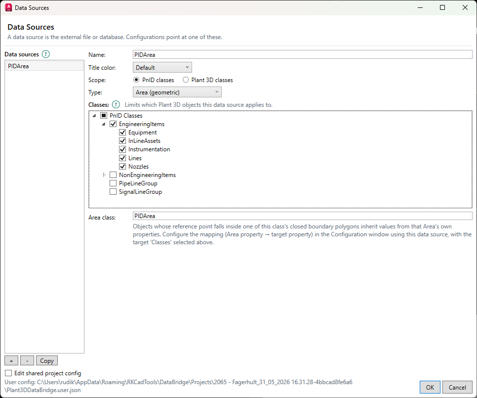
Open the RKCadTools tab → Data Bridge panel → Data Sources. You can also type P3DBRIDGE_DATASOURCES.
- Click + Add and give the source a clear name, e.g. P&ID Areas.
- Select PnID classes under Scope.
- Select Area (geometric) under Type.
- Under Classes, check the target classes that should receive values — e.g. valves and instruments. Checking a parent node includes its subclasses.
- Type the Area class’s exact internal name into Area class, e.g.
PidArea.
Create the configuration
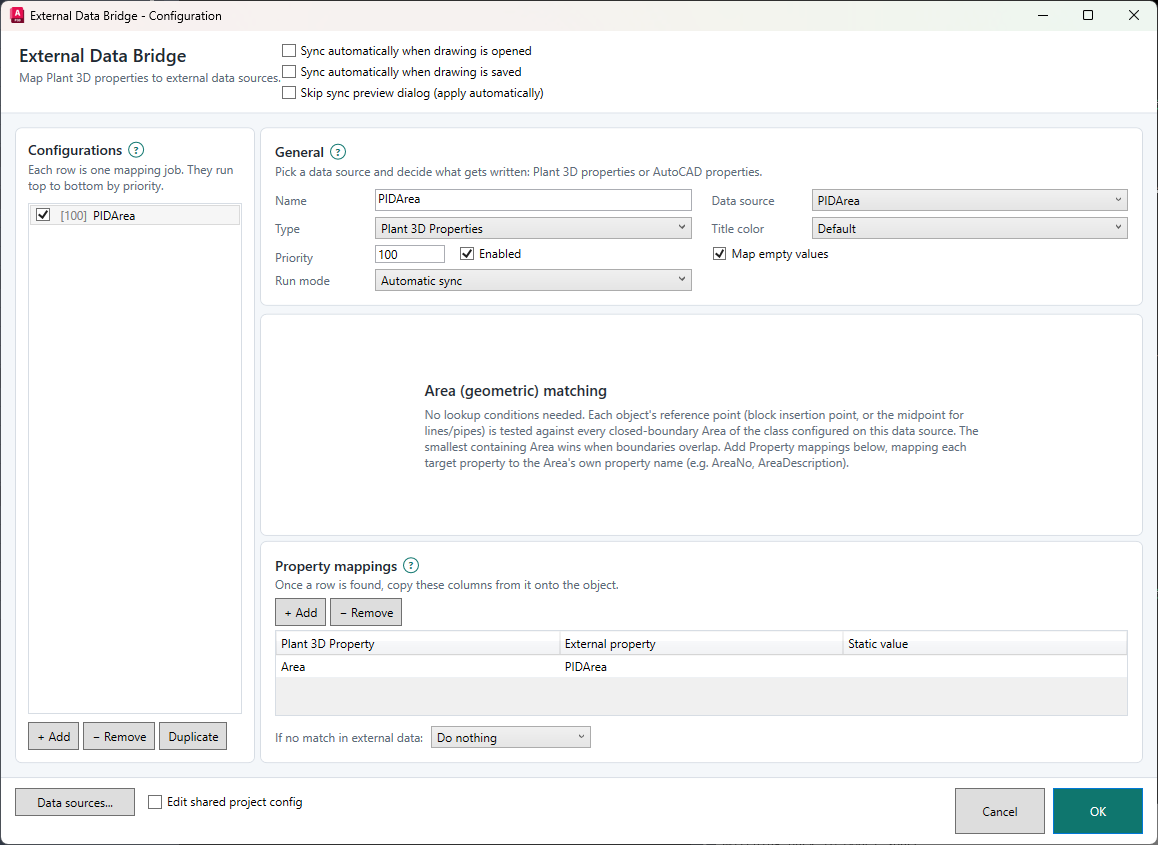
Open Setup in the Data Bridge panel, or type P3DBRIDGE_CONFIG.
- Click + Add under Configurations.
- Name the job, e.g. Inherit area properties.
- Select the data source you just created.
- Set Type to Plant 3D Properties.
- Use Automatic sync, and confirm Enabled is checked.
The Lookup conditions panel is now replaced by the text Area (geometric) matching. That’s correct — location inside the area is itself the match condition.
Map Area properties to the target objects
Add one row per property under Property mappings. The left side is the field on the target object; the right side is the field on the Area object.
| Plant 3D Property on the target object |
External property on Area |
Static value |
|---|---|---|
| AreaNo | AreaNo | leave empty |
| AreaDescription | AreaDescription | leave empty |
- Click + Add for each mapping.
- Select an editable target field in Plant 3D Property.
- Select the Area field in External property.
- Leave Static value empty when the value should come from the Area.
- Select Do nothing under If no match in external data. This keeps existing values on objects outside every area.
Only map to ordinary, editable Plant 3D properties. Acquired, inherited, calculated, read-only, and tag-format-controlled fields are not written directly. This feature also never overwrites TagNo.
Save and run a preview
- Click OK to save the configuration.
- Select Preview in the Data Bridge panel, or type
P3DBRIDGE_PREVIEW. - In the before/after view, confirm only the expected objects and properties change.
- Click Apply once the list looks right. Otherwise click Cancel and fix the setup.
Choose your day-to-day sync
After testing, users can run the sync manually or automatically.
P3DBRIDGE_PREVIEWP3DBRIDGE_SYNCP3DBRIDGE_SYNCOPENP3DBRIDGE_CONFIGAt the top of the configuration window you can also enable Sync automatically when drawing is opened and/or Sync automatically when drawing is saved. Keep the preview dialog turned on until the setup has been validated on a representative slice of the project.
How Data Bridge picks the right area
The insertion point is used as the reference point.
The curve’s actual geometric midpoint is used.
The center of the object’s bounding box is used as a fallback.
The geometrically smallest area wins, so a sub-zone can override a larger area.
The match becomes ambiguous. The object is skipped, and the sync result shows a warning.
Test the setup on a project copy
Use a copy of the project for the first test. Check items off as you go; the checkmarks are only saved in this browser on this computer.
Quick troubleshooting
No objects show up in preview
First check that the configuration is Enabled, that the data source uses the PnID scope, and that the target object’s class is checked under Classes. Then confirm that Area class is typed with the exact internal class name.
An Area row gets ignored
The linked drawing entity needs to be a closed Polyline, Polyline2d, or Polyline3d with at least three points. The sync result shows a warning if an Area row doesn’t have a usable closed boundary.
A visible object inside the box doesn’t match
It’s the reference point — not the whole symbol graphic — that’s tested. Check the insertion point for blocks and the midpoint for lines/pipes. For testing, move the object clearly away from the boundary.
The wrong area wins
The smallest area containing the reference point wins. With two equally sized overlapping areas, the object is skipped as ambiguous. Adjust the boundaries so they don’t overlap with the same area.
A property isn’t written
Check the mapping’s spelling and that the target field exists on the selected class. Acquired, inherited, calculated, read-only, and tag-format-controlled properties can’t be updated this way.
Old values remain on objects outside every area
That’s the safe, recommended behavior with “Do nothing”. Only choose “Clear values” if that’s a deliberate project requirement, and always check the changes in preview first.