Cable Tray guide for AutoCAD Plant 3D
Choose a product, draw a route, refine its connections, place supports and export quantities. Follow ten illustrated steps with the Cable Tray screenshots, from the ribbon to the Excel bill of material.
In this guide
- Before you start
- 1. Find the Cable Tray tools
- 2. Choose category, series and product
- 3. Set insertion reference and opening
- 4. Draw and continue a route
- 5. Extend and move components
- 6. Create branches and fittings
- 7. Compare Detailed and Lightweight
- 8. Manage sizes and BOM properties
- 9. Place and edit supports
- 10. Review quantities and export Excel
- FAQ, troubleshooting and final checks
Before you start
- Install and activate the matching RKCadTools build for AutoCAD Plant 3D 2025, 2026 or 2027 on Windows. Cable Tray is excluded from the Plant 3D 2024 build. See the installation guide if needed.
- Open a saved model in the active Plant project, in its 3D Piping area. Use model space with drawing units in millimetres or inches (
INSUNITS = 4or1). - Start with a project copy. Check that the configured CableTray and Support Library contains the series and articles you need.
- The examples show Scankab products. Available categories, series and fittings depend on your library; a fitting shown for one series may not be offered for another.
The current workflow selects products from the CableTray library. Older instructions that begin by selecting a project piping SPEC describe an earlier workflow.
1. Find the Cable Tray tools
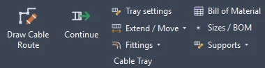
Open the RKCadTools ribbon while working in the project’s 3D Piping model. The Cable Tray panel contains route creation, editing, supports and quantity review.
2. Choose category, series and product
- Select Draw Cable Route.
- Open Category and choose Wire Mesh Trays, Cable Trays or Cable Ladders. The same category list also offers Supports as an entry to support placement.
- Choose a Product series. Use Search sizes to narrow the available sizes and articles.
- Open Dimension / product and choose the exact article. Check dimensions, material or finish and item number; the same section size can have several purchase variants.
- Rotate the product preview by dragging, scroll to zoom and double-click to reset it. Confirm the selected section before drawing.
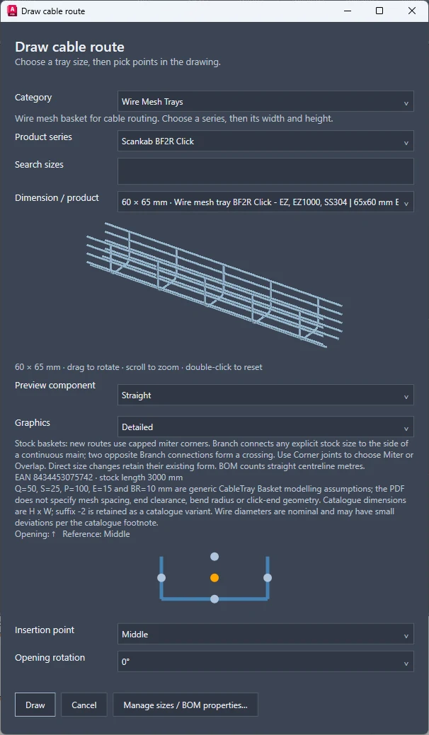
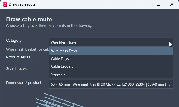
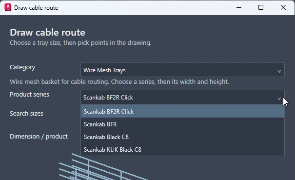
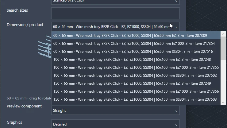
Commands: RKCADTOOLS_CABLETRAY_ROUTE
3. Set insertion reference and opening
For a new route, set Insertion point in Draw Cable Route before selecting route points: Middle, Bottom, Left, Right or Top. The highlighted point in the section diagram identifies the reference used for placement. Set the opening rotation and inspect the preview so the tray’s opening faces the intended direction.
For an existing route, use Tray settings to review the product, reference and opening. The Cable tray settings example shows Bottom, 0° rotation and Lightweight selected. Review the section diagram before applying the change.
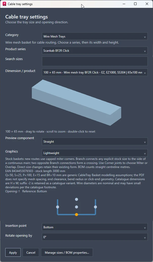
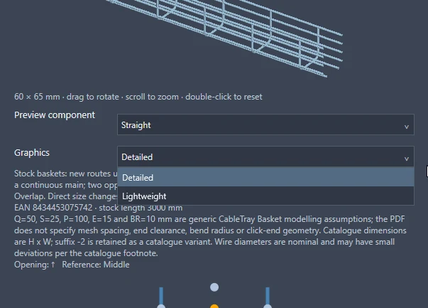
Choose Draw to begin a new route, or Apply when reviewing an existing route’s settings. Cancel closes the settings without applying the proposed choice.
Commands: RKCADTOOLS_CABLETRAY_EDIT
4. Draw and continue a route
- Click Draw, then pick the start point and subsequent route points in the model. Review the live 3D preview while positioning each segment.
- Follow the command prompts. Finish / Enter commits the route; Undo removes the last accepted step; Esc cancels the current drawing session.
- To extend the route from an open end, select Continue, pick the required open end and enter the next route points.
- Review the route and save the DWG normally. A saved route remains visible as ordinary DWG geometry without RKCadTools; creation and toolkit route editing require the plugin.
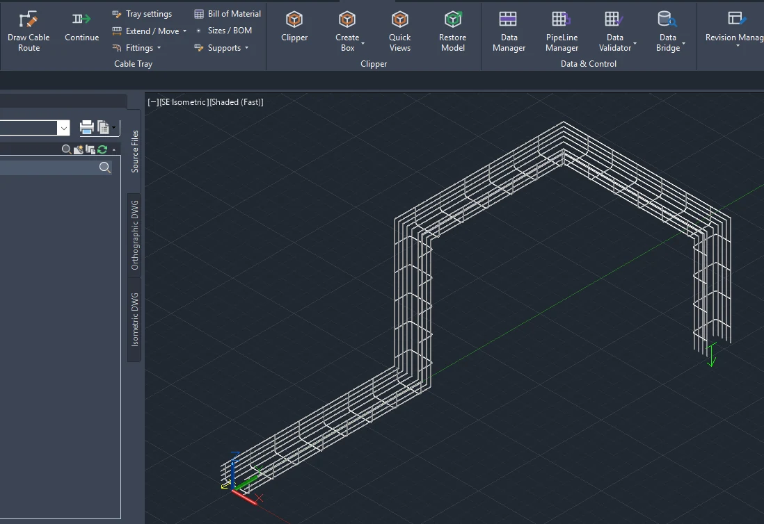
Commands: RKCADTOOLS_CABLETRAY_ROUTE, RKCADTOOLS_CABLETRAY_CONTINUE
5. Extend and move components
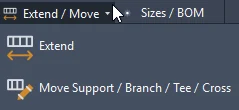
- Choose Extend / Move → Extend and select a straight section.
- Drag along the straight or type its final length in drawing units (millimetres or inches). Relative changes such as
+12or-6are also supported. Review the preview before accepting. - Use Move Support / Branch / Tee / Cross to slide the selected support or connection along the tray. Review the affected side assembly and confirm placement, or press Esc to cancel.
- After changing a route, check its connections and the placement of independent supports before saving.
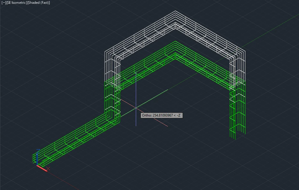
Commands: RKCADTOOLS_CABLETRAY_LENGTH, RKCADTOOLS_CABLETRAY_MOVE
6. Create branches and fittings
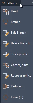
Use Fittings → Branch to connect a side route to a continuous main straight. Choose the connection’s position, side and exact stock article where offered, then draw the branch. Edit Branch reviews its position, side and profile; Delete Branch removes the branch and its descendants after review.
For stock wire mesh baskets, two opposite branches form a crossing. Corner joints chooses Miter or Overlap for stock baskets; Stock profile changes an exact stock article. Fitting-based series use their available tee, reducer or four-port cross products. A Bend starts at an open end and continues from its outlet.
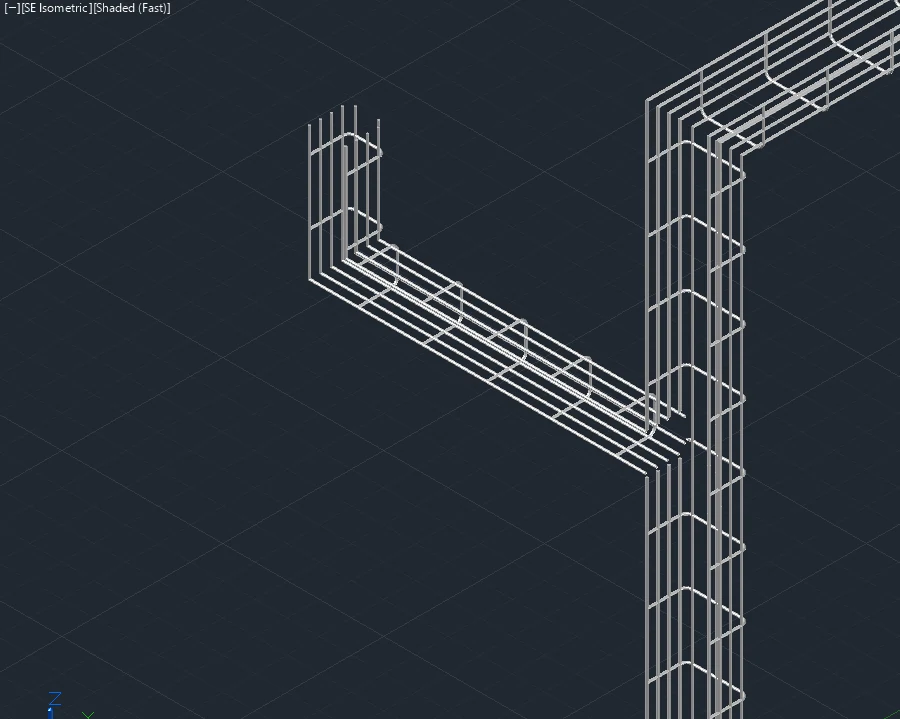
Commands: RKCADTOOLS_CABLETRAY_BRANCH, RKCADTOOLS_CABLETRAY_BRANCH_EDIT, RKCADTOOLS_CABLETRAY_BRANCH_DELETE, RKCADTOOLS_CABLETRAY_BEND, RKCADTOOLS_CABLETRAY_PROFILE, RKCADTOOLS_CABLETRAY_JOINTS, RKCADTOOLS_CABLETRAY_REDUCER, RKCADTOOLS_CABLETRAY_CROSS
7. Compare Detailed and Lightweight
Detailed shows mesh wires or ladder rungs. Lightweight replaces those details with a simplified route representation. Choose Fittings → Route graphics to change the display of a saved route. Its product, dimensions and BOM quantities stay the same.
Use Lightweight for everyday modelling. Detailed wire mesh trays can add substantial geometry and make the DWG large in MB or heavy to work with. Switch to Detailed only when preparing presentation views.
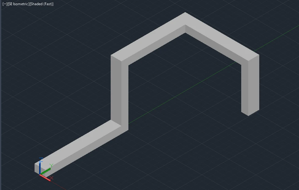
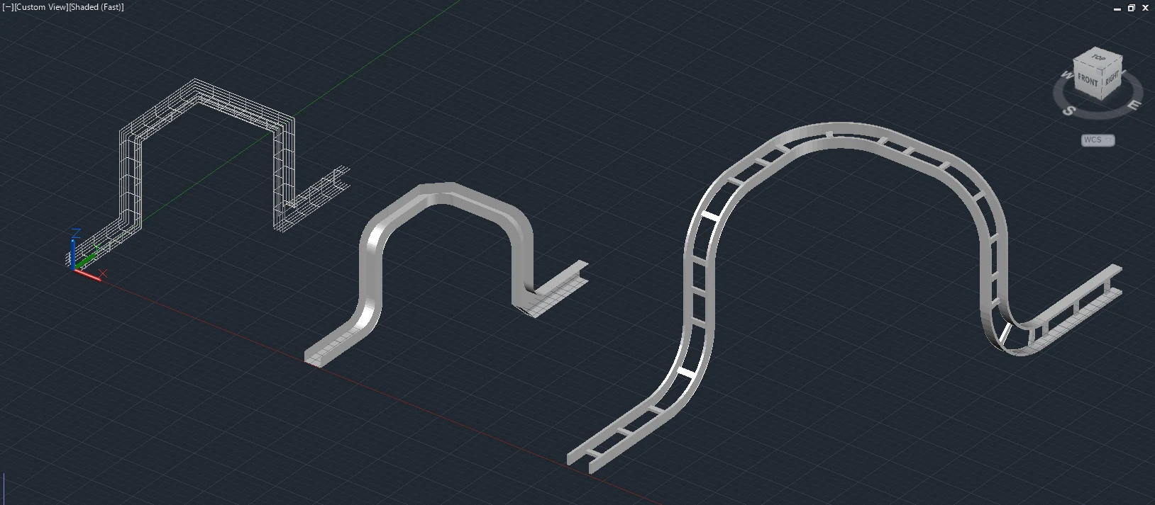
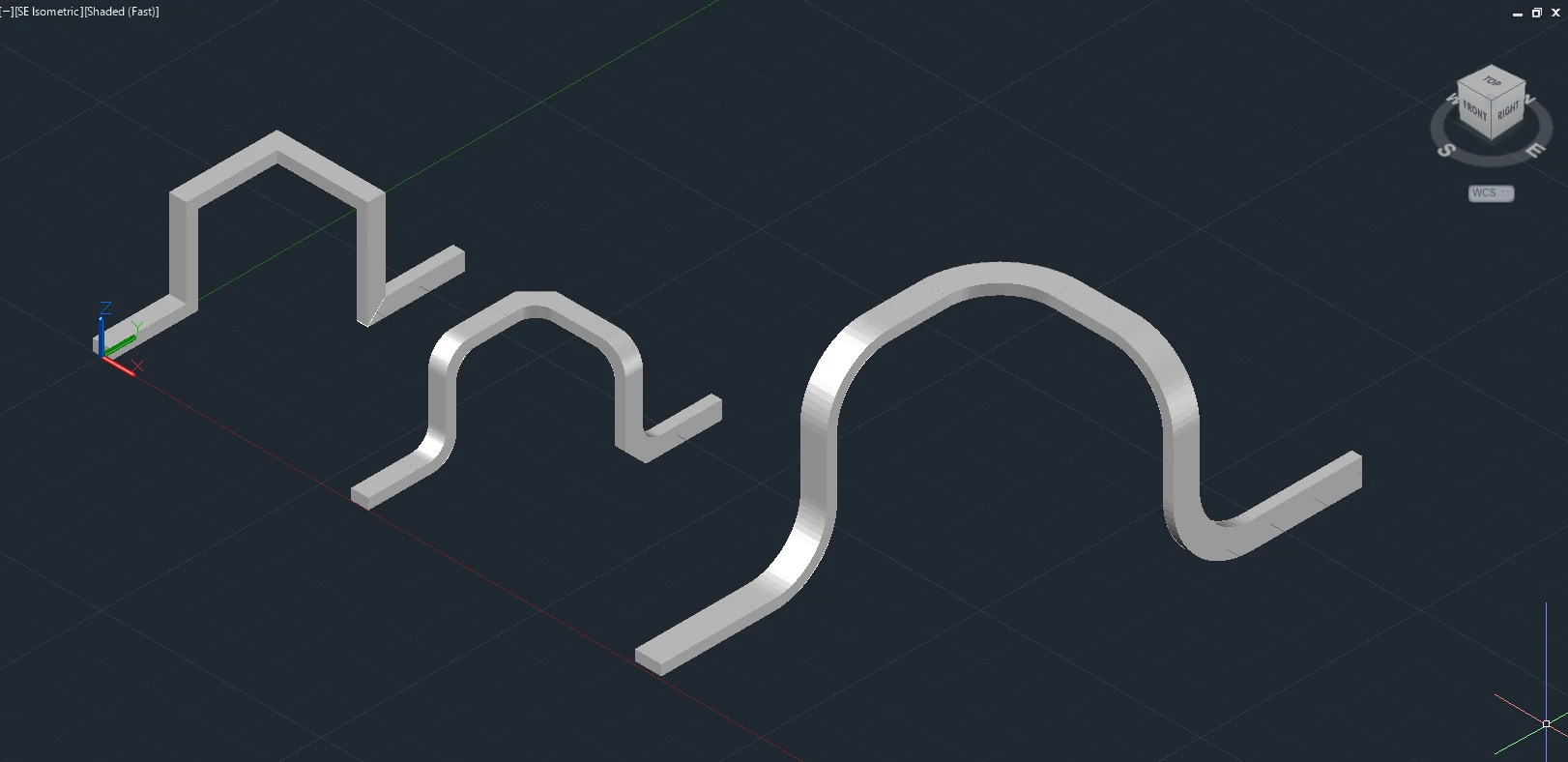
Commands: RKCADTOOLS_CABLETRAY_GRAPHICS
8. Manage sizes and BOM properties
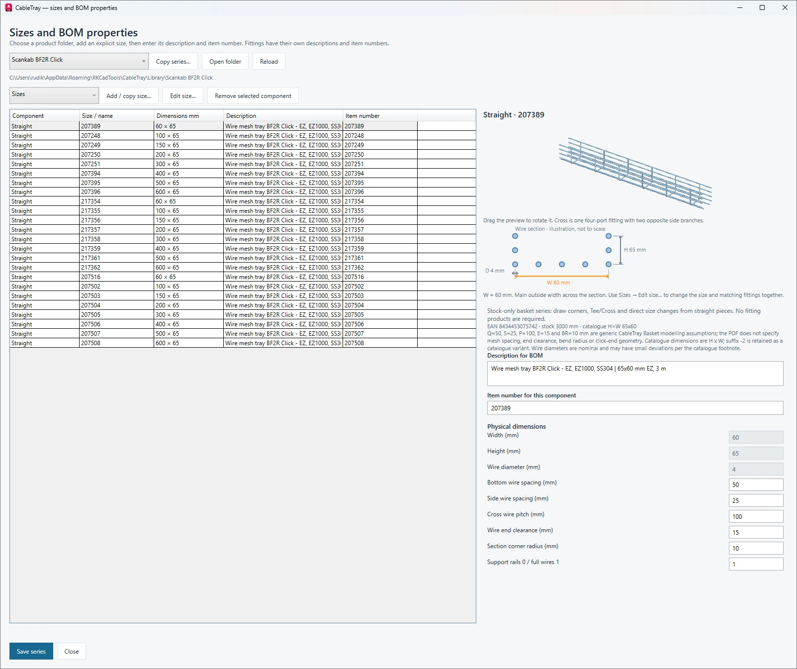
- Open Sizes / BOM from the ribbon or Manage sizes / BOM properties… in the route dialog.
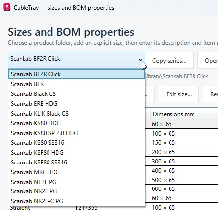
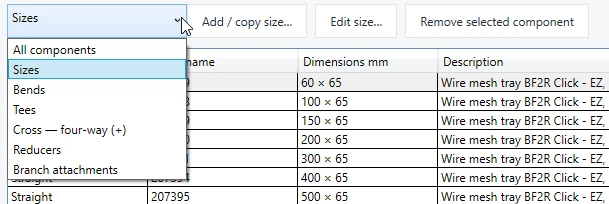
- Choose the required product series. Filter the table by Sizes, Bends, Tees, Cross, Reducers or Branch attachments, or show all components.
- Select an article and compare the preview, section dimensions, description and item number. Use Add / copy size or Edit size when changing the library.
- Keep geometry and purchase identity consistent, then select Save series. Support articles are managed under Support families. Review the choices offered when editing an already placed component.
Commands: RKCADTOOLS_CABLETRAY_LIBRARY
9. Place and edit supports
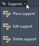
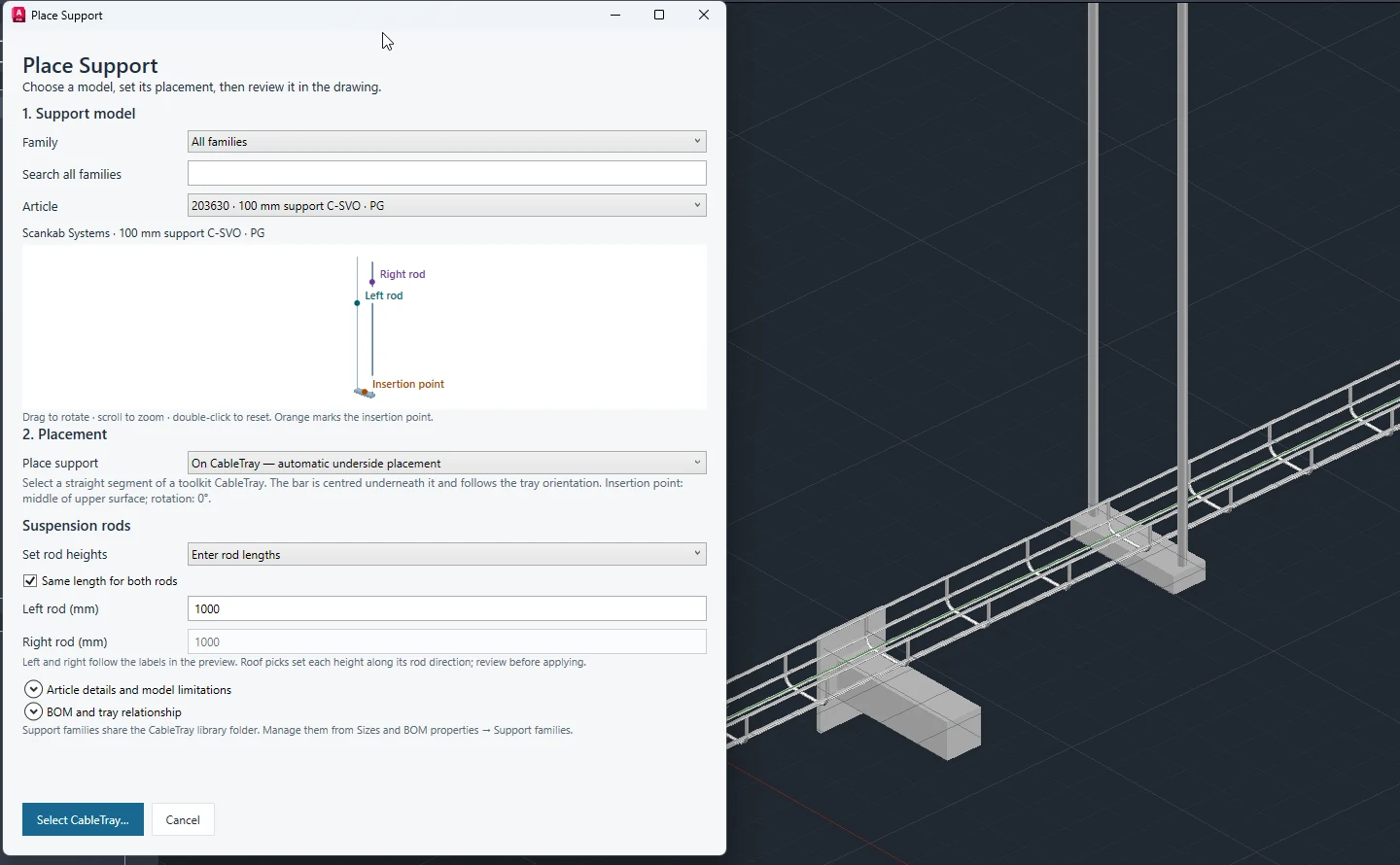
- Select Supports → Place Support. Search by family or article and inspect the support model’s labelled insertion point.
- For a suspended support, choose On CableTray — automatic underside placement and select a straight toolkit tray, or choose manual placement. Other models show their applicable placement controls.
- Set the suspension rod lengths. Use equal lengths where appropriate, or the available roof-point workflow to determine the required lengths. Check the left/right labels in the preview.
- Review the placement before applying it. Use Edit Support for later adjustments or Delete support to remove the selected support after review.
Supports remain independent. They do not automatically follow later tray changes. Check their position after route edits. Support quantities are counted separately from tray metres. Support spacing, loading and installation requirements remain part of the engineering design.
Commands: RKCADTOOLS_CABLETRAY_SUPPORT, RKCADTOOLS_CABLETRAY_SUPPORT_EDIT, RKCADTOOLS_CABLETRAY_SUPPORT_DELETE
10. Review quantities and export Excel
- Open Bill of Material in the Cable Tray panel.
- Check item numbers, descriptions, Count, Length (m), Qty and Unit. Use More columns for additional properties.
- Select a row to highlight matching components in the model. Move the window if it obscures the geometry. Use Clear highlight to remove the temporary highlight; it also clears when the window closes.
- Choose Export Excel…, select the destination and save the .xlsx workbook. Review the exported quantities before using them for a take-off.
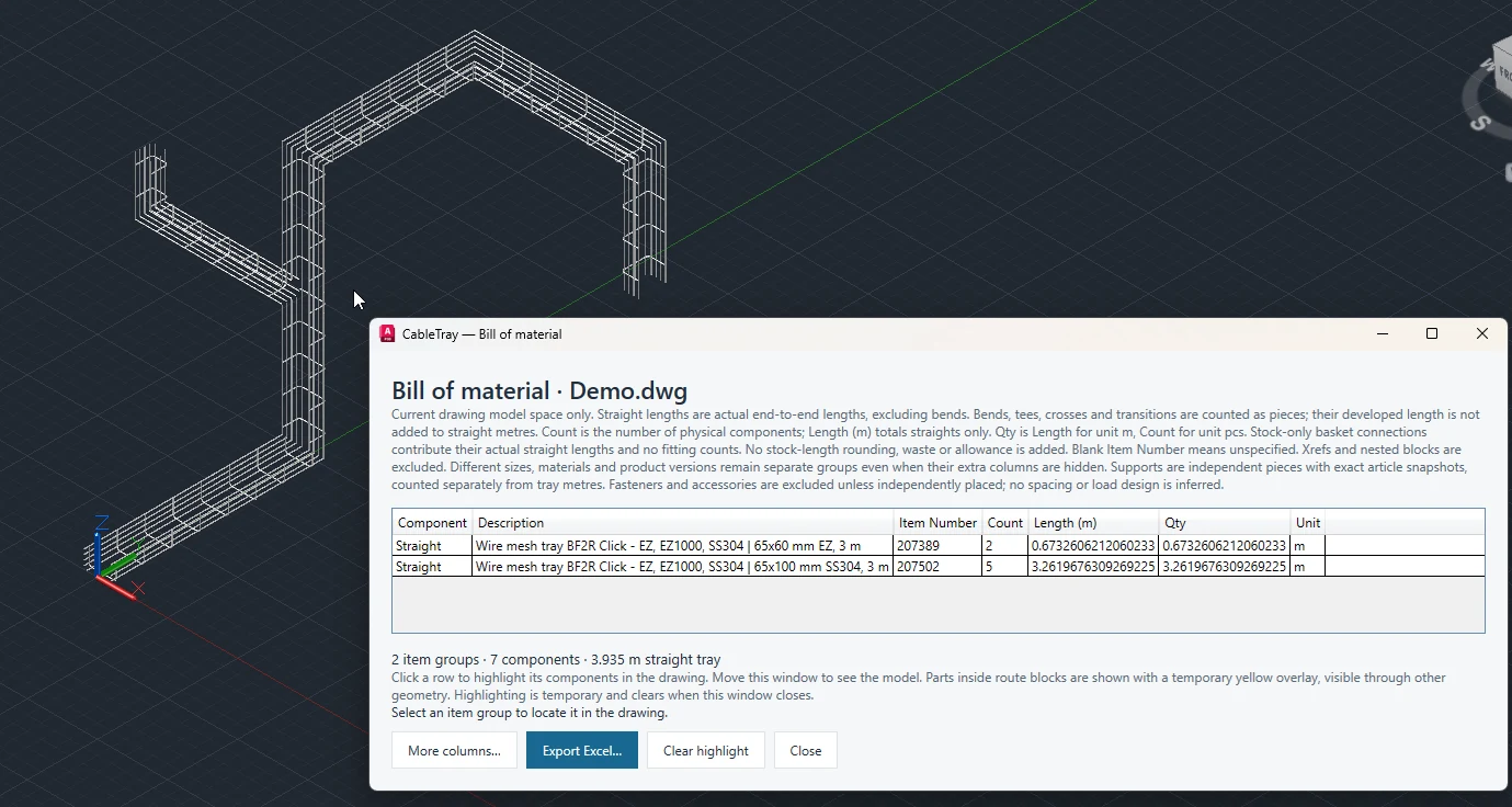
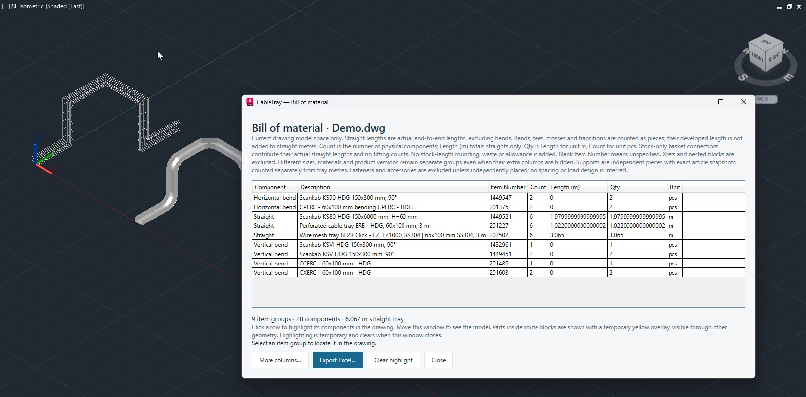
Understand the scope and units. The BOM covers the current drawing’s model space. Xrefs and nested block contents are excluded. Count is the number of physical components; Length (m) totals straight lengths. Qty uses length for metre-based items and count for piece-based items. Different sizes, materials and saved product versions stay in separate groups.
Straight quantities use actual end-to-end lengths and exclude bends. Fittings and supports are counted as pieces. Stock-only basket connections contribute their straight material without inventing separate fitting articles. Bend developed length, purchasing stock rounding, waste and installation allowances are not added to straight metres. Fasteners and accessories are excluded unless independently placed.
Commands: RKCADTOOLS_CABLETRAY_BOM
FAQ, troubleshooting and final checks
Why is my cable tray drawing large in MB or slow to work with?
Detailed wire mesh trays are typically the heaviest option because of the many individual wires. Select the route, open Fittings → Route graphics and use Lightweight for everyday modelling. Switch to Detailed only for presentation views. The display choice preserves the product dimensions and BOM quantities.
No products or sizes appear
Check the configured CableTray and Support Library folder, choose the intended category and series, and clear any size search. Open Sizes / BOM to inspect the available articles. An empty or missing library needs the required product data before routing can begin.
A fitting or route edit is unavailable
Check that you selected the required open end or straight segment and that the chosen series contains the fitting or stock article needed for that operation. Stock wire mesh connections use different tools from fitting-based series. Follow the command-line explanation for a rejected edit and cancel if the preview does not match your intent.
A support is no longer under the tray
Supports do not have a persistent association that makes them follow every tray edit. Review the support’s position and use the support editing or Move command to adjust it, then check its rod lengths and placement.
The BOM differs from a purchasing take-off
Confirm you are reviewing the intended current DWG. Check excluded xrefs and nested blocks, metre versus piece units and each saved article’s identity. Add purchasing stock rounding, waste, installation allowances and other engineering provisions in your separate take-off workflow as appropriate.
- Check route openings, bends and branch connections in the model.
- Review independent supports after route changes.
- Verify item numbers and quantities, export the Excel workbook and save the DWG.
- Use the Cable Tray quick start for a short command reference, or return to the feature overview.