Cable Tray for Plant 3D.
Route. Support. Quantify.
Draw wire mesh trays, cable trays and cable ladders directly in AutoCAD Plant 3D. Choose a product and size, build the route in 3D, place supports, and review an Excel-ready bill of material.
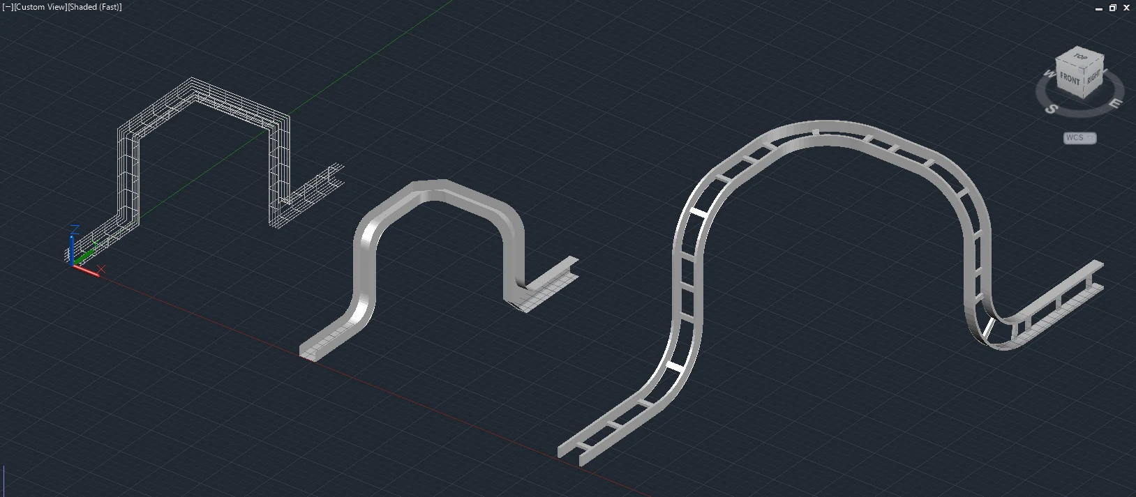
Cable tray routing, from product selection to quantities
Work on the cable route inside the Plant 3D model, with product selection, geometry and quantity review in the same workflow.
Choose the actual product
Select a category, manufacturer series, dimension and item number from your CableTray library. Inspect the rotating preview before drawing.
Adjust the route in context
Continue from an open end, extend a straight, add a branch or supported fitting, and review the change in the model.
Review quantities by item
Keep descriptions, item numbers and sizes together. Check straight lengths and component counts, then export the drawing’s BOM to Excel.
Wire mesh trays, cable trays and cable ladders
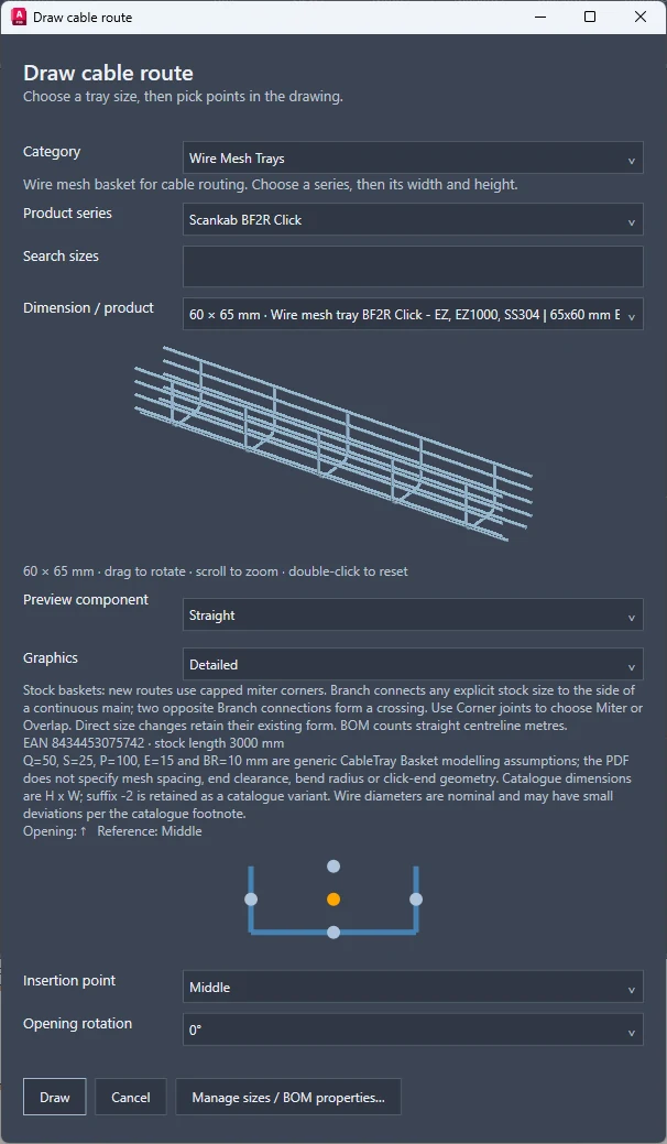
Open Draw Cable Route in the Cable Tray ribbon panel. Choose Category, Product series and Dimension / product. The supplied examples show Scankab products; available series depend on your configured library.
Choose Middle, Bottom, Left, Right or Top as the insertion reference and set the opening rotation. Rotate or zoom the preview to check the section before selecting route points.
Sizes / BOM lets you manage library sizes, descriptions, item numbers and support families. Keep each product variant and its purchase identity consistent.
A practical cable routing workflow
1. Choose
Open a saved millimetre or inch model in the active Plant project. Select your tray category, series and exact product.
2. Draw
Pick route points while reviewing the 3D preview. Follow the command prompts to finish, undo a point or cancel.
3. Adjust
Use Continue, Tray settings, Extend / Move and Fittings to refine the route. Available fittings depend on the series.
4. Review
Place the required supports, check Bill of Material and export the current drawing’s quantities to an Excel workbook.
Follow the Cable Tray quick start, with commands and screenshots →
Open the Cable Tray deep dive: 10 steps and 22 screenshots →
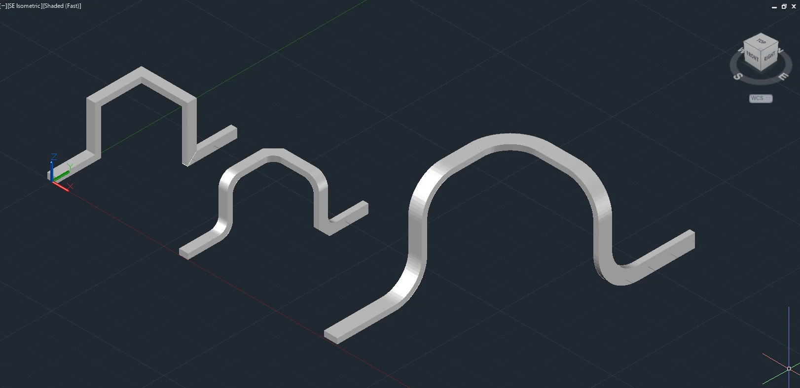
Detail when you need it. A clear route overview when you don’t.
Detailed shows individual mesh wires or ladder rungs. Lightweight simplifies the display to make the route’s position and bends easier to see. Use Lightweight for everyday modelling, especially with wire mesh trays, and switch to Detailed only for presentation views.
Switch with Fittings → Route graphics. The saved product, dimensions and BOM stay the same. Use Branch for side connections; stock wire mesh crossings use two opposite branches. Fitting-based series use their available tee or cross products.
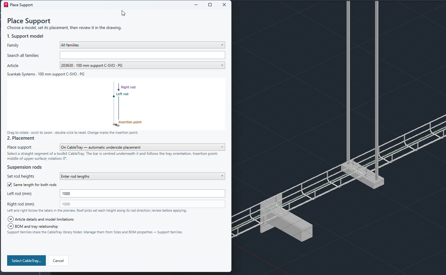
Place and edit cable tray supports
Open Supports → Place Support, search by family or article, and check the preview’s insertion point. Suspended supports offer automatic underside placement on a straight CableTray segment or manual placement; other models offer their applicable placement controls.
Enter suspension rod lengths or use the available roof-point workflow. Use Edit Support to adjust an existing support and Delete support to remove one after review.
Supports are independent components: they do not automatically follow later tray changes. Their quantities are counted separately from tray metres. Review support spacing, loading and installation requirements as part of your engineering design.
Cable tray bill of material and Excel export
Open Bill of Material to review components in the current drawing’s model space. Select a row to highlight matching items in the model, or use Clear highlight to remove the temporary highlight. Use More columns for additional properties, then choose Export Excel… to save an .xlsx workbook.
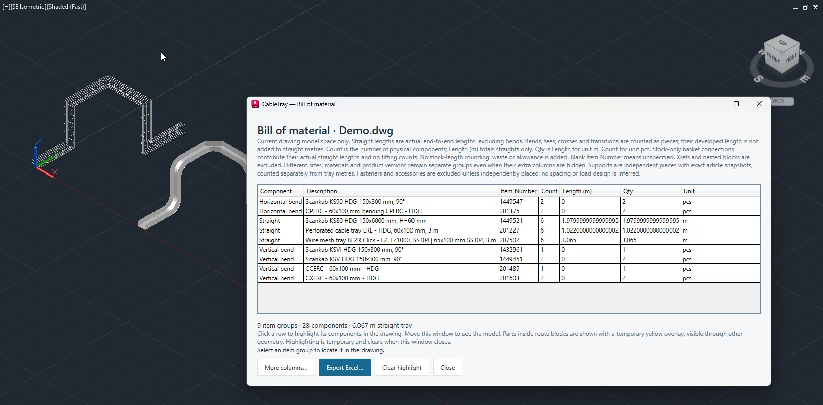
Straight quantities use actual end-to-end lengths in metres, excluding bends. Fittings and supports are counted as pieces; stock-only basket joints contribute their straight material without inventing fitting articles. Xrefs and nested block contents are excluded. Stock rounding, waste, installation allowance and bend developed length are not added to straight metres. Fasteners and accessories are excluded unless independently placed.
Cable Tray questions
Which Plant 3D versions include Cable Tray?
Cable Tray is included in the RKCadTools builds for AutoCAD Plant 3D 2025, 2026 and 2027 on Windows. The Plant 3D 2024 build does not include this feature. Use a saved millimetre or inch model in the active project’s 3D Piping area.
Do I need to choose a Plant piping spec?
The current Draw Cable Route workflow selects from the CableTray product library using category, product series and dimension. Use Sizes / BOM to manage available articles and product data.
Can others see the route without RKCadTools?
Routes are saved as ordinary DWG geometry with toolkit route data. The geometry remains visible without RKCadTools; creating or editing the toolkit route requires the plugin.
Why is my cable tray drawing large in MB or slow to work with?
Detailed wire mesh trays are typically the heaviest option because they contain many individual wires. Use Lightweight for everyday modelling and switch to Detailed only for presentation views. Select the route and use Fittings → Route graphics to change its display. Product dimensions and BOM quantities stay the same.
Does Lightweight change the quantities?
No. Route graphics changes the presentation of the same saved product and assembly. Dimensions and BOM quantities are preserved.
Does the BOM include every project drawing?
No. Bill of Material reviews the current drawing’s model space. Xrefs and nested block contents are excluded. Open and review the relevant drawings separately.
Start your first Cable Tray route
Install the RKCadTools build for your Plant 3D version, open a copy of your model, and follow the Cable Tray quick start.